Chain survey is the simplest method of surveying. In this survey only measurements are taken in the field, and the rest work, such as plotting calculation etc. are done in the office. This is most suitable adapted to small plane areas with very few details. If carefully done, it gives quite accurate results. The necessary requirements for field work are chain, tape, ranging rod, arrows and some time cross staff.
Amongst the various methods of surveying, the commonly used method is called chain surveying. For less precise works chain is used whereas, for more accurate and precise work other types of surveys are used.
Principles of Chain Surveying:
The principle of chain surveying is to provide a skeleton framework of straight lines, which can be plotted to scale if the lengths of these lines are pre-determined either with a chain or a tape.
The framework must mostly consist of triangles.
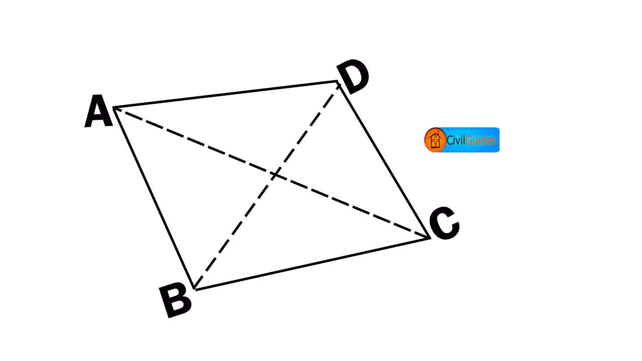
For example, if all the four sides of the figure “ABCD” are known, the figure cannot be plotted unless we know at least the magnitude of one angle.
But if we divide the figure into two triangles by a diagonal AC or BD whose length has previously been determined, the plotting is possible due to the formation of triangles of known sides.
Or in other words, if the lengths AB, BC, CD, DA, and BD are known, the quadrilateral ABCD can be plotted without knowing any angle.
Base Line:
The longest chain line in chain surveying is often called the base line. It is the most Important line, fixes up the directions of all other lines.
Since the accuracy of the whole survey work depends upon the accuracy of the base line, it should be laid off on the ground level as much as possible.
Base Line should pass through the center of the area. It is measured very accurately, and all the necessary corrections are applied.
Check Line:
The mistakes made in the measurements as well as in plotting any of the lines may distort the actual figure. Which is liable to pass unnoticed.
These mistakes could be avoided by performing the whole survey twice or thrice, but this may also be discovered by making cross measurements which are called proof lines or check lines.
For example, The quadrilateral ABCD in the below Figure can be plotted even if only the lengths of AB, BC, CD, DA, and BD are known, but the mistake in any line cannot be detected unless it is significant enough to change the shape of the figure. Or it is such that two sides of a triangle appear less than the third side.
For this reason, the length of the other diagonal AC scaled from the plan should be equal to its length measured on the ground. This line will enable the checking of the plotting, and hence it is called “check line”.
The check lines indicate the correctness of the work. The location of check lines depends upon the local circumstances, as well as on discretion of the surveyor.
In general, a check line is one which joins some fixed points on any two sides of a triangle.
Tie line
A“tie line” is that line which joins some fixed points called “stations” on the main survey lines. The purpose of a tie line is two-fold, i.e, firstly it enables checking of the accuracy of the network and secondly locating the interior details which are comparatively far away from the main survey lines.
Offsets:
The details like corners of buildings, roads, fences, etc, included within the sketch of the survey, are measured by lateral measurements with respect to main survey lines. These measures are called offsets.
Offsets are of two types.
(i) Perpendicular offsets.
This is the most common method of locating objects. The perpendicular distance measured from a known chainage point on the main line to the object is called the perpendicular offset.
(ii) Oblique offsets.
The measurements which are not made at right angles to the survey lines are called “tie-line offsets” or “oblique offsets.”
Principles of chain Surveying.
(i) First of all, the site should be inspected with a view to find a suitable location of stations.
(ii) The survey lines should be as few as practicable and such that the framework may be plotted.
(iii) If possible, a base line should be run roughly through the middle of the area on which the framework of triangles covering the major portion of the area may be built up.
(iv) All the triangles should be well conditioned, i.e. no angle should be less than 30° or greater than 120° in a triangle.
(v) Each portion of the survey should be provided with check lines.
(vi) The offsets should be short; particularly for locating features which are important. A number of subsidiary lines or tie lines should be run to locate the details and to avoid long offsets.
(vii) As few lines as possible should be run without offsets.
(viii) The obstacles to ranging and chaining should be avoided as far as possible.
(ix) The lines should lie as far as possible on the ground level.
(x) In lines lying along a road, the possibility of interruption during chain surveying, a line at one side of the road should be drawn.
(xi) The main Stations should be inter-visible and the main principle of surveying, i.e, working from the whole to the part, should be strictly observed.
(xii) The lines should be measured in an order avoiding unnecessary walking between stations
Chain Surveying Procedure:
For chain surveying, at least two men are required, but frequently three people are employed.
They are:
(1) The surveyor, who does the reading and booking,
(2) The leader, and
(3) The follower.
(i) To start the chaining of a line the follower holds the zero end of the chain in contact with the peg at the beginning of the line and presses the handle with his feet and stands firmly over it.
(ii) The leader holds another end of the chain and goes along with the arrows and ranging rods on the line.
(iii) Nearly at the end of the chain length, he stops and aligns with the help of ranging rod which he keeps vertical and faces the follower, who gives him instructions by his arms.
(iv) After alignment, the leader pulls the chain and inserts an arrow in the ground to mark the end.
(v) The lateral measurements or offsets are taken from the chain line to any object that is to be plotted on the plan.
(vi) The chain line should be such that these offsets are as short as possible. While pulling the chain, care should be taken.
(vii) After taking the offsets, the leader picks up the ranging rods and remaining arrows keeping the chain a little away from the line so that the arrow placed is not disturbed, starts moving ahead as before.
(viii) As the follower reaches the arrow with the near end of the chain, he should speak loud “chain” or “tape” to give a warning to the leader that he has nearly reached the arrow or a chain length and immediately the leader Stops.
(ix) The follower holds the handle against the arrow and directs the leader to come in line as before.
(x) The leader again stretches the chain and fixes the arrow in the ground at another chain length or make a cross if the ground is firm.
(xi) Again, the leader walks in the line in the same manner and the follower now picks up the first arrow, comes to the second arrow and gives instructions for the third chain length.
(xii) Thus, the whole process is repeated until the end of the line is reached.
(xiii) The number of arrows with the follower is an indication of the number of full chain lengths completed at any time.
(xiv) After some time the number of arrows should be checked mutually by the follower and the leader so that no chain length is missed and no arrow is lost.
Generally, the number of arrows taken is ten and hence after fixing the tenth arrow, the leader speaks out “arrows” which means that this was the tenth chain line.
(xv) The follower then goes to the tenth arrow and picks it up after fixing a ranging rod there. The arrows are then handed over to the leader, and a record is made in the field book by the surveyor.
(xvi) For the fractional length of the Chain, the leader stretches the chain beyond the end station. While the follower holds the rear handle of the chain against the last arrow.
The leader reads the fractional chain length loudly and the
surveyornotes the entire length of the line.
Duties of the follower and leader During Chain Surveying.
The duties of the follower (Chain man at the rear end of the chain) are;
(i) To give signals and instructions to the leader.
(ii) To place the leader in the line of the ranging rod.
(iii) To carry the rear handle.
(iv) To pick up the arrows.
The duties of the leader ( the chain man at the forward end or head ) are;
(i) To stretch the chain forward.
(ii) To insert the arrow at every chain length.
(iii) To obey the directions given by the follower.
Recording the measurements in the Field Book.
The field book is an oblong book with a hinge at the narrow edge and the chain is represented in it by one or two red lines or blue lines ruled down centrally along the length of each page.
The booking or recording of the field work is commenced from the bottom of the first page. The double line book is better because the main chain line readings are separated from offset readings.
The station points are lettered or numbered, and a small rectangle or triangle is drawn in the field book to enclose the chaining figure at the station points.
The lines meeting at the station point are also marked and the reference sketches are drawn on field book, and after this line survey, lines are run by chaining.
When a chain survey is to be conducted the necessary equipment should be taken, and reconnaissance or preliminary inspection, of the area should be made. By this inspection the surveyor can judge the network.
Wooden pegs & ranging rods mark the station points. Then, the stations are marked the reference sketches are drawn on field book, and after this the survey lines are run by chaining.
Precautions.
The following points should be kept in view while booking the field notes.
(i) All the measurements should be recorded as soon as they are taken.
(ii) Each chain line should be recorded on a separate page of the field book.
(iii) Figuring and writing should be neat, and legible Overwriting of the figures should be avoided completely.
(iv) The notes should be complete, and nothing should be left to memory.
(v) Notes should be so full and neat that the draftsman who is unfamiliar with the area surveyed may plot easily
(vi) Neat reference sketches should be given in the field book, and explanatory notes should be added.
(vii) The field book should be kept clean, and no entry should be made in it,nor it should be rubbed. If an entry is wrong, a line should be drawn through it, and the count entry is made over it.
if an entire page of the Field book is to be discarded, it should be crossed and marked canceled and reference of the other page in which the correct entries are made, should be given on the canceled page.


 ft. This chain is commonly used in cadastral survey.